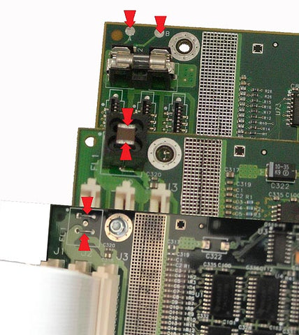
0B0006 Trailing Cable Test Points
Posted by Bob Wert on
Any time the Designjet 1050C trailing cables are disconnected and reconnected because of a carriage replacement, belt replacement, trailing cable replacement or main logic PCB replacement, the resistance check MUST be made or risk blowing F7 or the main logic board itself.
AFTER the trailing cables are attached, you need to read at least 100 ohms across the test points (more typically closer to 1000 ohms). The resistance will be moving and that is normal. Zero ohms means a short and the trailing cables will need to be reseated. HP put the ground and +5VDC .030” apart on the connector and it is impossible to see if all 3 connections are correctly seated. You must use the ohmmeter.
Share this post
1 comment

I have a 1050c whose main board does not look like any board in the picture above. I can’t see any test points.